1/26/2016

GAS TURBINE COMPRESSORS


  1. When compared with axial compressors, centrifugal compressors have the following five advantages:
    They occupy a smaller length than the equivalent axial compressors.
  2. They are not liable to loss of performance by buildup of deposits on the surfaces of the air channel when working in a contaminated atmosphere.
  3. They are able to operate efficiently over a wider range of mass flow at any particular rotational speed (i.e., they alleviate problems of matching operational conditions with those of the associated turbine).
  4. They are used mainly in small power units because the higher isentropic efficiency of axial compressors cannot be maintained for small machines.
  5. Titanium is the preferable material because of its high resistance to corrosion.

Principle of Operation

The centrifugal compressor consists of a stationary casing containing a rotating impeller, which increases the velocity of the air, and a number of diffusers that decelerate the air converting a part of its kinetic energy to pressure. Figure 1 illustrates a centrifugal compressor.

Compressor Characteristics

 the variation in the pressure ratio when a valve placed in the delivery line of the compressor running at constant speed is slowly opened. When the valve is shut and the flow is zero, the pressure ratio will have a value A. This is the pressure head that is produced by the action of the impeller on the air trapped between the vanes. As the valve is opened and the flow increases, the maximum efficiency is reached at point B. Any further increase in flow will result in a decrease of the pressure ratio. If the flow is increased significantly beyond the design flow, the efficiency decreases rapidly. A hypothetical case is reached at point C where the pressure ratio drops to unity (i.e., all the power absorbed by the compressor is dissipated in friction losses). In reality, point A could be obtained if desired. However, most of the curve between points A and B could not be obtained due to the phenomenon of surging. Surging is associated with a sudden drop in delivery pressure, and with violent aerodynamic pulsations that are transmitted throughout the machine. Assume that the compressor is operating at some point D. A decrease in mass flow should be accompanied by a fall of delivery pressure. If the pressure of the air downstream of the compressor does not fall quickly enough, the air will flow backward due to the pressure gradient. This results in a rapid drop in pressure ratio. The pressure downstream of the compressor drops as well until the compressor reestablishes the flow. The surging of the air may not happen immediately. This is because the pressure downstream of the compressor may fall at a greater rate than the delivery pressure. As the mass flow is reduced, the flow reversal will occur. The conditions between points A and B are inherently unstable. If the operating point is on the part on the curve having negative slope, a decrease in mass flow results in increase in delivery pressure. The flow characteristic in this region is stable.


FIGURE 1 Diagrammatic sketches of centrifugal compressors. (a) Impeller and diffuser of a centrifugal
compressor; (b) impeller of a centrifugal compressor; (c) different compeller of a centrifugal compressor;
(d) impeller shroud.

In a gas turbine, the swallowing capacity of the components downstream of the compressor (e.g., the turbine) and the way the swallowing capacity varies over the range of operating conditions determines the actual point at which surging occurs. An additional limitation exists in the operating range between points B and C. As the mass flow increases and the pressure decreases, the density is reduced and the radial component of velocity must increase (m AV). Point E is reached where no further increase in mass flow can be obtained and choking occurs.

FIGURE 2 Theoretical characteristic.

This point represents the maximum flow obtainable at the articular rotational speed. Other curves can be obtained for different speeds. Figure 3 illustrates the actual variation of pressure ratio over the complete range mass flow and rotational speed. The left-hand extremities of the constant-speed curves are joined up to form what is known as the surge line. The right-hand extremities represent the points where choking occurs.
Since the isentropic p-T relation is given by:
Therefore, the form of the curves of the temperature ratio plotted on the same basis will be similar to the pressure ratio plotted. The isentropic efficiency curves are plotted in Fig. 3. The efficiency varies with the mass flow at a given speed in a similar manner to the pressure ratio. However, the maximum value for all speeds is approximately the same. A curve representing the locus of operating points at maximum efficiency is shown in Fig. 3. Gas turbines are usually designed to operate on this curve.


1/06/2016

GENERAL GUIDELINES HSE (HEALTH, SAFETY & ENVIRONMENT)


HISTORY HSE

Traditional Era (1750 BCE)

Code of Hammurabi: Act early work safety


The Industrial Revolution (1750-1850)

Changes in work systems, use of engine power, introduction of new methods of processing raw materials, organization of work, Emerging diseases associated with exposure

Industrialization era

K3 developments following the use of technology (PPE and Safety Equipment)


Management era

H.W Heinrich: Domino Theory
Frank Bird and Germain: The theory of causation Loss Model
ISO, SMHSE, OHSAS 18001


REGULATION LEGISLATION & LEGAL BASIS

UU No. 1 of 1970: Safety

UU No. 13 of 2009: Job Agency

UU No. 22 of 2001: Oil and Gas

UU No. 32 of 2009: Protection and Management of LH

MPR (Mijn Politie Reglement) No. 341 of 1930

Regulation No. 19 of 1973: Regulation and Supervision of Safety in Mining

Government Regulation No. 35 of 2004: Upstream Oil and Gas

Regulation No. 34 of 2005: Amendment to Government Regulation No. 35 of 2004 Upstream Oil and Gas

Mining candy No. 02 / P / M / Pertamb / 1975: Safety at Pipe Fittings Suppliers and facilities for Transportation of Oil and Gas Excluding Oil and Gas Mining Concession Area

Kepmentamben No. 300.K / 38 / M.PE / 1997: Safety Pipe Distributors of Oil and Gas

ESDM No. 045 of 2006: Management of Drilling Mud, Mud Waste and Drill powder on Drilling Activity Oil and Gas

1/05/2016

Drilling Rig (Jenis-jenis RIg)

Drilling rig is an installation of equipment to drill into underground reservoirs for water, oil, or gas, or mineral deposits underground. Drilling rig could be on land (onshore) or at sea / offshore depending on the needs of its user. Although the offshore rig can drill down to the bottom of the sea to search for minerals, technology and economics of underwater mines can not be done commercially. Therefore, the term "rig" refers to a collection of tools used to carry out drilling on the surface of the Earth's crust to sample the oil, water, or mineral. In a drilling installation, especially for oil and gas and geothermal drilling, typically using the specifications of the equipment that is able to work at a high enough pressure rating ranging from 2000 psi up to 15,000 psi.Rigs drilling for oil and natural gas can be used not only to identify the geological characteristics of the reservoir, but also to create a hole that allows the retrieval content of oil or gas from the reservoir.System main drilling rig consists of:1. Hoisting System

System lifter (Hoisting System) is one of the main components of the rig that serves to help the system tools player in drilled wells by providing tools that fit and work space required to lift and lower the drill string, casing string and subsurface equipment (underground) Other and from the wellbore. Lifting system consists of two (2) sub main parts, namely:1.1. Supporting frame (Supporting Structure) is a steel frame construction which is assembled or built on the point of wells (drilling site) whose job it is to support a series of drill pipe equipment and other equipment used by players to drill holes system.Supporting framework (Supporting Structure) consists of: a. Substructure is a large steel construction purposes are built to be the basis and support the drill tower whose height is determined by the needs of wild bursts deterrent. This substructure into the workplace for activities above and below the rig floor.

b. Drilling tower (Derrick / Mast) function of derrick is to provide space for the lifting or enter a series of drill pipe or into the wellbore. The higher the derrick, the longer the series of drill pipe that can be handled, so the faster the process of making a trip operation.


1.2. Lifting equipment (Hoisting equipment)

Is a special equipment for lifting, lowering and hang a series of drill pipe (consisting of Drill Pipe, Drill Collar, etc.) And drill bit (Drilling bits) in the wellbore.Lifting equipment consists of:a. Drawwork engine unit towing / lifting Strong (winch) located near a table on the floor Rig player.

b. Overhead Tools (Tools Upper)A "chain link" in the lifting system consisting of: - Crown Block: Unit wheels / pulleys-pulley (sheaves-sheaves) located at the top of the tower of drilling.- Travelling Block:The composition of the wheels / pulleys-pulley (sheaves-sheaves) are hung under the crown block above the drill floor. Together with the crown block pulley hoist system formed. - Hook (hook):The hook-shaped tools which are located below the traveling block in which the swivel and a series of drill pipe hanging during drilling operations.- Elevator:Tweezers are very strong and hung on the lick (hanger elevators) associated side Travelling block or hook. These elevators are used to decrease or increase the portions series drill pipe to and from boreholes.c. Drilling Line


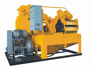
High-strength steel wire rope which is a liaison from Drawwork, Crown Block and Block Travelling to attract other overhead equipment in lowering their duties, draw or hang a series of drill pipe and others.2. Circulating SystemCirculating System is a part of the main system that functioned in a drilling rig to circulate drilling mud, drilling down through a series of pipes and climbed into the annular carrying powder permukaan.Aliran drill to drill mud when circulation will pass through parts: a. Mud mud tank to pump b. Mud high pressure pump to the connection surface and into drillstring c. Drillstring to bits d. Bit up through the annulus to the surface e. Until the surface is going through solid control equipment, such as;1. Shale Shaker

2. Desander

3. Desilter

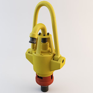
4. CentrifugeIt is aimed at cutting filtration of drilling mud that mud back to the suction tank (suction pit) back clean. And keep repeating until the completion of drilling work.Travelling in the mud of the bit to the surface will bring a lot of information including the rock sample in the form of cutting, it is also sometimes at a particular location will bring non-hydrocarbon gas such as H2S, CO that are harmful to living things around the place.3. Rotating SystemRotating system (system player) is one of the components - the main components of a drilling rig. Its main task is rotating drill bit, drill a burden and give the channel a high-pressure mud into the drill bit to drill to make the hole. The player system consists of four main sub-components:Swivel (head cleansing)

Rotating Assembly (Unit player)

Petroleum System


Five Key Elements of Petroleum Geology


What the Petroleum System?

Petra: Stone
Oleum: Oil


Terminology concerning the search for oil and gas with reference to the disciplines of geology
A geological concept with a closed system which explains the presence of oil and gas

ORIGIN PETROLEUM → inorganic

THEORYOIL FROM volcanic activity (Vesuvius)

Mendeleyeff Chain Reaction
Supporters of the theory: Von Humbold & Gay Lussac (1805), Virlet d'Aoust (1834), Berthelot (1866), Mendeleyeff (1877)

Example: Ghawar Field (Russia), 60 Billion Barrel Oil remained controversial until now

Picture3.png

Supporters of the theory: Haquet (1794), Tissot (1974), etc.

Properly used in the Mahakam (No significant Volcanic Activity)
Debate 'Chicken - Egg' Which is the first

All oil companies embrace this theory, except Russia


Five Key Elements of Petroleum Geology

Picture4

1.Source Rock

2.Reservoir Rock
3.Timing / Maturation / Migration
4.Cap Rock
5.Trap


CONCLUSION


- Petroleum Geology is a concept that describes the search for oil and gas based disciplines of geology
- Five Key Elements is very important in the search for oil and gas


Petrolium System so on, you can visit other topic :
GENERAL GUIDELINES HSE (HEALTH, SAFETY & ENVIRONMENT)
Drilling Rig

 May you have concern to improve my blog, please comment on below.

Thanks.